How to Design a Fired Heater
An introduction to sizing calculations a fired heater
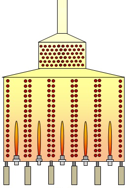
Multi-burner lane Cabin Fired Heater
STEP 1
The first step in designing a fired heater involves calculating the size of the Radiant Section. In order to get a first approximation of the size, some reasonable assumptions and/or restrictions must be made. For example:
Assumption 1: 70% of the duty is absorbed in the radiant section and 30% will be absorbed in the convection section
Assumption 2: Let’s consider a tube size of 6"NB (168.3mm OD)
Assumption 3: Let's also consider that we are designing a Vertical Cylindrical type fired heater
Now, lets say that we wish to design a fired heater to satisfy the following requirements:
1) Total absorbed duty of 10 MW
2) A maximum flux of 31,000 W/m2 is permitted in the radiant section
STEP 2
Now considering that the duty required is 10 MW and we assume that 70% of this duty is absorbed in the radiant section, we can therefore calculate the total radiant section duty will be 7 MW.
7 MW = 7,000,000 W
Given that we have a flux limit of 31,000 W/m2, we can therefore calculate the surface area required to satisfy the flux limit:
7,000,000 / 31,000 = 225.8 m2
STEP 3
Assuming the tube diameter of 6"NB (0.1683 m OD), we can calculate the total length of exposed tube with the following general equation:
Pi * Diameter * Pipe Length = Pipe Surface Area
Rearranging the equation:
Pipe Length = Pipe Surface Area / ( Π * Diameter )
Pipe Length = 225.8 / (Π * 0.1683 )
= 427.1 m
STEP 4
As the type of heater we are designing (Vertical Cylindrical) has vertical tubes, we will consider a maximum straight tube length of 18.3 m (as per API 560). These means that we can calculate the number of tubes using the general equation:
No. Tubes = Total Pipe Length / Individual Tube Length
= 427.1 / 183
= 23 tubes
Now, as we are using 6"NB tubes, they will be spaced at 2 * NB between each tube (i.e. tube pitch). This means that the space between each tube will be: 12 inches (0.3048 m).
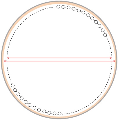
Radiant Section of Vertical Cylindrical Fired Heater Plan View
STEP 5
As the tubes are in a circular arrangement, we can calculate the total circumference of the arrangement of tubes using the equations below:
Circumference = Tube Pitch * No. of Tubes
= 0.3048 * 23
= 7.01 m
Tube Circle Diameter = Circumference / Π
= 2.23 m
STEP 6
Things will now begin to get a little more tricky because we have to ensure that there is sufficient space available to position our burners within the tube circle arrangement. The total required duty of the heater is 10 MW and the burners will therefore be releasing typically 20% greater heat (depending upon how efficient we wish to design the heater). This means that our burners will typically release a total of ~12 MW.
Assuming that there will be multiple burners (in order to increase the reliability/availability of the heater), it is unlikely that the burners will be able to safely fit within a tube circle diameter of 2.23 m.
We will therefore need to increase the tube circle diameter by increasing the number of tubes. However, bear in mind that in order to maintain a constant exposed tube surface area, we will also reduce the height of the tubes as we increase their total number. Reducing the height of the tubes, will also mean therefore reducing the height of the radiant section.
Bear in mind also that API 560 Fired Heater Design Standard specifies safety limits to ensure adequate spacing around each burner (i.e. minimum clearance from the burners in the floor to the arch (radiant roof)).
STEP 7
Considering these factors, lets try 42 tubes, with a tube length of 10.6 m each. This will give the following results:
Tube Circle Diameter: 4.077 m (which is just sufficient to fit 4 burners safely)
Total Tube Surface Area: 224.2 m2 (reasonably close to the target of 225.8m2)
This solution is a good approximate first iteration toward a viable and competitively designed heater.
Things to consider...
Please note that there are some simplifications and some important aspects that are not mentioned within this article to allow for simplicity. For example, the following considerations are also important:
Even tube no. requirement: For modern VC heaters, the process fluid terminals (inlets and outlet) are both located at the top of the radiant section. This means that an ‘even’ no. of tubes are required within the radiant section. Hence, our initial consideration of 23 tubes would not be viable.
Return Bends: The return bends on each tube are also located within the firebox and hence contribute toward the exposed surface area for heat transfer. Therefore, some consideration for this should be applied when calculating the total number of tubes.
Tubes per pass and no. of passes: The process fluid within the tube will have a specified maximum allowable pressure drop that must be satisfied. This means that the no. of passes within the radiant section will have to be adjusted accordingly, which in turn impacts upon the total number of tubes within the radiant section that are actually feasible.
Burner layout symmetry: In order to maximise uniformity of heat release within the firebox, the burners should be symmetrically arranged within the firebox. Often, the no. of burners will be equal to the no. of passes, but this is not always the case. In addition, there are burner to burner clearances that are specified by the burner manufacturers that must be respected and will determine the suitability of the available tube circle diameter.
As you'd expect, an experienced fired heater design engineer can intuitively consider the above mentioned factors and converge on a reasonable design solution in a few minutes.
Convection Section
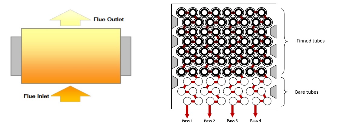
Convection Section Design Layout
This article is a general introduction into some of the main considerations necessary when designing the Convection Section of a Fired Heater. The detailed heat transfer calculations and correlations are not detailed within this article (for more details on such procedures, please feel free to contact us).
The main purpose of the convection section is to absorb energy from the hot flue gas leaving the radiant section. The convection Section usually consists of bare and finned tube bundles and plays a crucial role in maximising the efficiency of the heater. As the name suggests, the primary mode of heat transfer within this area is ‘Convective’.
Often the lowest 2 or 3 rows are bare tube, whilst the remaining rows are typically finned tubes. The purpose of the fins is to increase the surface area for heat transfer. The heater designer will use a combination of no. of tube rows, the length of the tubes and the extent of finning, in order to adjust the surface area for heat transfer.
There are 3 main type of extended surfaces that are most commonly used in Convection Sections tubes, as shown below:
Convection Section Tube Types
Studs are most commonly used with heaters firing Fuel Oil, since deposits from the flue gas can more easily be cleaned from studded tubes than Serrated or Solid Finned tubes, which are more commonly used for heaters firing gaseous fuels. Sootblower lanes are usually incorporated into the design to allow for tube cleaning (either by manual steam lances or automated retractable systems).
Note: API 560 defines the acceptable dimensions of each of these extended surface types.
Fired Heater Simulation Results - Convection Section
One of the important areas of consideration is the pressure drop of the flue gas as it flows over the tube bundles. The size of the stack is directly influenced by this factor, since a larger stack will be required to create sufficient draft to overcome these flue losses and maintain -2.5 mm(H2O)g at the arch (as per API 560 requirements).
One way of mitigating the impact on the stack size is to utilise an Induced Draft Fan (ID Fan), which will be designed to pull the flue gas through the tube bundle and any associated ducting.
Appropriate Size for Radiant Section
The Convection Section is usually mounted on top of the Radiant Section (although some designs may have ‘off-set’ convection sections). This means that designer will have to carefully select the ‘Number of Rubes Per Row’ AND the ‘Tube Length’ appropriately in order to fit inside the radiant section footprint.
In addition, the heater designer needs to ensure that the No. of Tubes Per Row is suitable for the overall number
Additional Process Streams
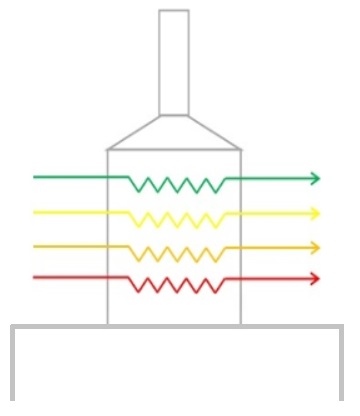
Convection Section Multiple Process Streams
Flue Gas Pressure Drop
The convection section also offers a convenient location for heating additional process streams, such as Steam Generation or Boiler Feed Water (BFW). The tubes with these streams may have a different tube size and ‘No. of Tubes Per Row’ to the main process coils. The additional of such secondary process streams can help to improve the overall efficiency and energy management of the site in general, not just the heater.
Refractory Insulation
The convection section is usually lined with Castable Refractory, with the hot face usually having the robust/dense layer material. However, in recent years, convection sections are commonly being designed with Ceramic Fibre lining in order to minimise weight and ramp up times during start up (which must be steadily carried out when using Castable refractory).


