Fired Heater Design Configurations
API 560 Furnace and Fired Heater Design Layouts
API 560 General Design Layouts of Fired Heaters and Furnaces
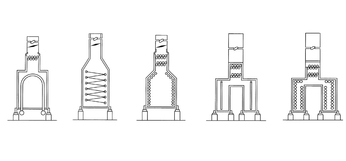
API Standard 560 is an internationally recognised code which defines the design of Fired Heaters. Most of the heaters built in recent years, will fit into one of the 3 main design configurations:
- Vertical Cylindrical (Vertical Serpentine coils arranged within a cylindrical firing section)
- Cabin Heater (Horizontal radiant coils within a firing box)
- Box Heater (Vertical radiant coils within a firing box)
Each of the designs mentioned above may have multiple radiant firing zones, depending upon the amount of energy required by the feedstock process.
(Please note: there are other configuration of API heaters, however, these aren't discussed within this article)
The fired heater design layout is determined during the early calculation stages and will largely depend upon the amount of energy required, the type of process (feedstock) fluid and the physical footprint constraints. We'll take a quick overview for some of the most common uses of each type.'
Vertical Cylindrical Fired Heater Design
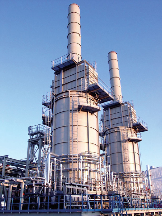
Vertical Cylindrical Fired Heaters
These are perhaps the most common fired heater design in recent years, likely due to their cost efficient layout, relative ease of transportation and smaller footprint.
Vertical cylindrical heaters are commonly used for utility feedstocks such as Thermal Oils and Ethylene Glycol, but are also used for Reboiler and Reactor Feed services.
With most of the refractory surface inside the heater being shielded with coils, contributes to the cost efficiency of the layout and smaller footprint in comparison to the other fired heater design options.
Cabin Fired Heater Design
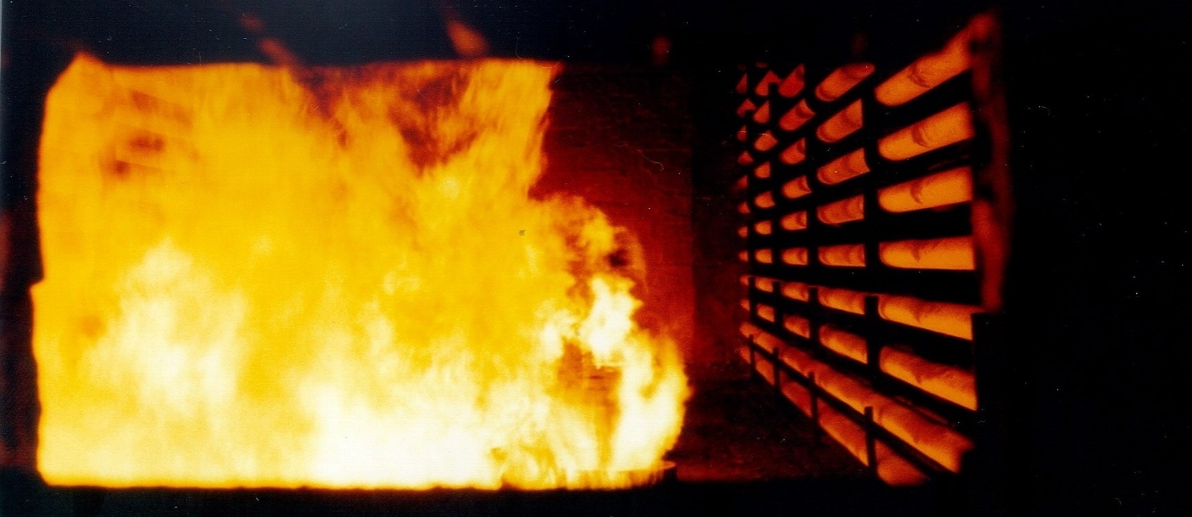
Flames and Tubes inside Cabin Fired Heater
This design of fired heater is often the preferred choice for crude feedstock process fluids. The horizontal coils means that the process fluid can be readily drained for maintenance and cleaning activities.
The ability to readily drain and clean tubes is an important maintenance activity for Crude Heaters, as a internal coke / fouling layer deposit inside the tubes during operation.
The Cabin Heater design is typically characterised by wall mounted coils along the longest side of the firing box, with the end walls left clear for viewing ports.
Cabin heaters are also inherently more capable to mount larger convection sections than VC heaters, which can be a preferred when designing fired heaters with larger duties.
Box Fired Heater Design
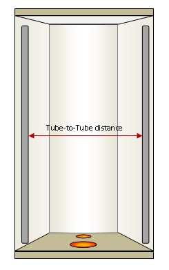
Box Fired Heater Design with Vertical Tube Coils
This design of fired heater is probably less common than the preceding two, but can be used to somewhat to merge the benefits of the VC and Cabin designs.
For example, similarly with Cabin heaters, the Box Heater design is also inherently capable to mount larger convection sections to accommodate large duty requirements. In addition, similarly with VC heaters, the Box Fired Heater design also benefits from a cost efficient tube support configuration.
However, one of the downsides of having vertical tubes is that the process fluid is not readily drainable, which can be a very important requirement for fluids that are prone to coking.
If you'd like to learn more about the subjects discussed within this article, or need any assistance with your project, please feel free to get in touch


