We use cookies to improve user experience on our website. By using our website, you consent to the use of these cookies.
We use cookies to improve user experience on our website. By using our website, you consent to the use of these cookies.


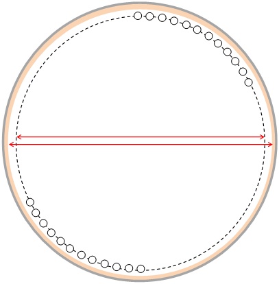
Vertical Cylindrical Radiant Section Sketch (Plan View)
As the tubes are in a circular arrangement, we can calculate the total circumference of the arrangement of tubes.
Circumference = Tube Pitch * No. of Tubes
= 0.3048 * 23
= 7.01 m
Tube Circle Diameter = Circumference / Π
= 2.23 m
Things will now begin to get a little more tricky because we have to ensure that there is sufficient space available to position our burners within the tube circle arrangement. The total required duty of the heater is 10 MW and the burners will therefore be releasing typically 20% greater heat (depending upon how efficient we wish to design the heater). This means that our burners will typically release a total of ~12 MW.
Assuming that there will be multiple burners (in order to increase the reliability/availability of the heater), it is unlikely that the burners will be able to safely fit within a tube circle diameter of 2.23 m.
We will therefore need to increase the tube circle diameter by increasing the number of tubes. However, bear in mind that in order to maintain a constant exposed tube surface area, we will also reduce the height of the tubes as we increase their total number. Reducing the height of the tubes, will also mean therefore reducing the height of the radiant section.
Bear in mind also that API 560 has safety limits to ensure that a minimum height is not exceeded (i.e. minimum clearance from the burners in the floor to the arch (radiant roof)).
Considering these factors, lets try 42 tubes, with a tube length of 10.6 m each. This will give the following results:
Tube Circle Diameter: 4.077 m (which is just sufficient to fit 4 burners safely)
Total Tube Surface Area: 224.2 m2 (reasonably close to the target of 225.8m2)
This solution is a good approximate first iteration toward a viable and competitively designed heater.
Please note that there are some simplifications and some important aspects that are not mentioned within this article to allow for simplicity. For example, the following considerations are also important:
Even tube no. requirement: For modern VC heaters, the process fluid terminals (inlets and outlet) are both located at the top of the radiant section. This means that an ‘even’ no. of tubes are required within the radiant section. Hence, our initial consideration of 23 tubes would not be viable.
Return Bends: The return bends on each tube are also located within the firebox and hence contribute toward the exposed surface area for heat transfer. Therefore, some consideration for this should be applied when calculating the total number of tubes.
Tubes per pass and no. of passes: The process fluid within the tube will have a specified maximum allowable pressure drop that must be satisfied. This means that the no. of passes within the radiant section will have to be adjusted accordingly, which in turn impacts upon the total number of tubes within the radiant section that are actually feasible.
Burner layout symmetry: In order to maximise uniformity of heat release within the firebox, the burners should be symmetrically arranged within the firebox. Often, the no. of burners will be equal to the no. of passes, but this is not always the case. In addition, there are burner to burner clearances that are specified by the burner manufacturers that must be respected and will determine the suitability of the available tube circle diameter.
As you'd expect, an experienced fired heater design engineer can intuitively consider the above mentioned factors and converge on a reasonable design solution in a few minutes.
COVID-19 secure
something wrong
something wrong
Thank you for getting in touch.
We use cookies and other technologies to improve the browsing experience on our website.
By using our website, you consent to the use cookie technologies.