We use cookies to improve user experience on our website. By using our website, you consent to the use of these cookies.
We use cookies to improve user experience on our website. By using our website, you consent to the use of these cookies.

This article is a general introduction into some of the main considerations necessary when designing the Convection Section of a Fired Heater. The detailed heat transfer calculations and correlations are not detailed within this article (for more details on such procedures, please feel free to contact us).
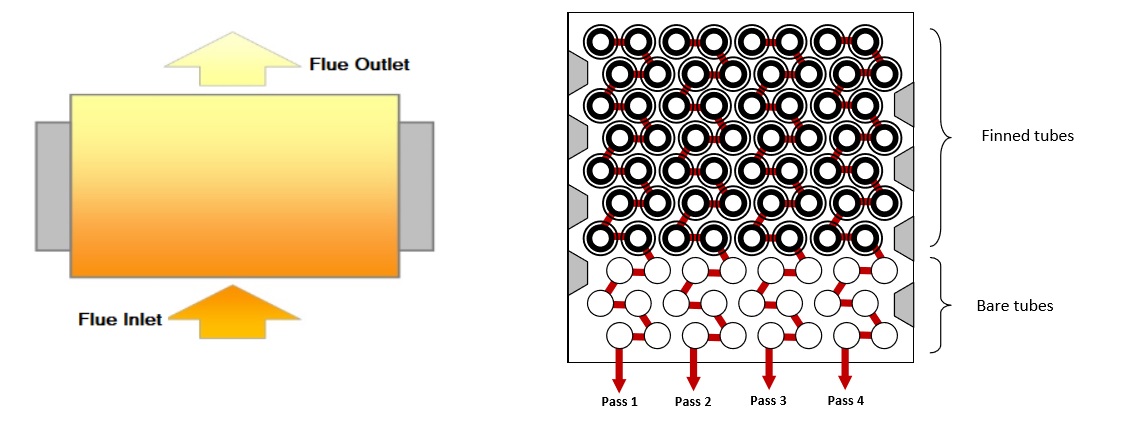
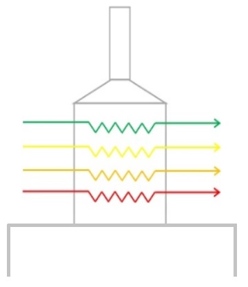
The main purpose of the convection section is to absorb energy from the hot flue gas leaving the radiant section. The convection Section usually consists of bare and finned tube bundles and plays a crucial role in maximising the efficiency of the heater. As the name suggests, the primary mode of heat transfer within this area is ‘Convective’.
Often the lowest 2 or 3 rows are bare tube, whilst the remaining rows are typically finned tubes. The purpose of the fins is to increase the surface area for heat transfer. The heater designer will use a combination of no. of tube rows, the length of the tubes and the extent of finning, in order to adjust the surface area for heat transfer.
There are 3 main type of extended surfaces that are most commonly used in Convection Sections tubes, as shown below:

Convection Section Tube Types
Studs are most commonly used with heaters firing Fuel Oil, since deposits from the flue gas can more easily be cleaned from studded tubes than Serrated or Solid Finned tubes, which are more commonly used for heaters firing gaseous fuels. Sootblower lanes are usually incorporated into the design to allow for tube cleaning (either by manual steam lances or automated retractable systems).
Note: API 560 defines the acceptable dimensions of each of these extended surface types.

One of the important areas of consideration is the pressure drop of the flue gas as it flows over the tube bundles. The size of the stack is directly influenced by this factor, since a larger stack will be required to create sufficient draft to overcome these flue losses and maintain -2.5 mm(H2O)g at the arch (as per API 560 requirements).
One way of mitigating the impact on the stack size is to utilise an Induced Draft Fan (ID Fan), which will be designed to pull the flue gas through the tube bundle and any associated ducting.
The Convection Section is usually mounted on top of the Radiant Section (although some designs may have ‘off-set’ convection sections). This means that designer will have to carefully select the ‘Number of Rubes Per Row’ AND the ‘Tube Length’ appropriately in order to fit inside the radiant section footprint.
In addition, the heater designer needs to ensure that the No. of Tubes Per Row is suitable for the overall number of process flow passes within the heater.

The convection section also offers a convenient location for heating additional process streams, such as Steam Generation or Boiler Feed Water (BFW). The tubes with these streams may have a different tube size and ‘No. of Tubes Per Row’ to the main process coils. The additional of such secondary process streams can help to improve the overall efficiency and energy management of the site in general, not just the heater.
The convection section is usually lined with Castable Refractory, with the hot face usually having the robust/dense layer material. However, in recent years, convection sections are commonly being designed with Ceramic Fibre lining in order to minimise weight and ramp up times during start up (which must be steadily carried out when using Castable refractory).
If you need any assistance with your heater project, please feel free to get in touch
COVID-19 secure
something wrong
something wrong
Thank you for getting in touch.
We use cookies and other technologies to improve the browsing experience on our website.
By using our website, you consent to the use cookie technologies.