This is a Read-only view. Open the file to launch and activate all features
HeaterSIM - Fired Heater Simulation Results
Online API Fired Heater Software
| ENERGY PERFORMACE | ||
| Total Absorbed Duty | MW | 11.997 |
| Total Heat Release | MW | 13.962 |
| Total Efficiency | % | 85.931 |
| PROCESS | ||
| Process Name | Therminol XP | |
| Heat Duty | MW | 11.997 |
| Flow rate (sec) | kg/s | 40 |
| INLET CONDITIONS | ||
| Inlet Temperature | °C | 200 |
| Inlet Pressure | kPa a | 750.1 |
| OUTLET CONDITIONS | ||
| Outlet Temperature | °C | 306.9 |
| Outlet Pressure | kPa a | 410.879 |
| AIR | ||
| Air Flow | kg/s | 5.765 |
| Air Temp. | °C | 15.5 |
| Excess Air | % | 20 |
| FUEL | ||
| Fuel Flow | kg/s | 0.279 |
| Fuel LHV | kJ/kg | 50015 |
| Fuel Mol. Wt. | 16 |
| STACK | ||
| Flue Gas Flow | kg/s | 6.044 |
| Flue Gas Temp. | °C | 273.5 |
| CO2 | mol% | 8.06 |
| H2O | mol% | 16.06 |
| N2 | mol% | 72.67 |
| O2 | mol% | 3.21 |
| SO2 | mol% | 0 |
| CONVECTION | ||
| Convection Sect. No. | 1 | |
| Heat Duty | MW | 3.943 |
| Flue Gas Flow | kg/s | 6.044 |
| Max Tube Temp. | °C | 295.5 |
| Total Press. Loss (inc. gain) | mmH2O | -1.59 |
| RADIANT SECTION | ||
| Radiant Cell | 1 | |
| Heat Duty | MW | 8.055 |
| Heat Release | MW | 13.962 |
| Arch Temp. | °C | 788.2 |
| Max Tube Temp. | °C | 353.2 |
| Average Flux | W/m² | 34605 |
| Maximum Flux | W/m² | 57481 |
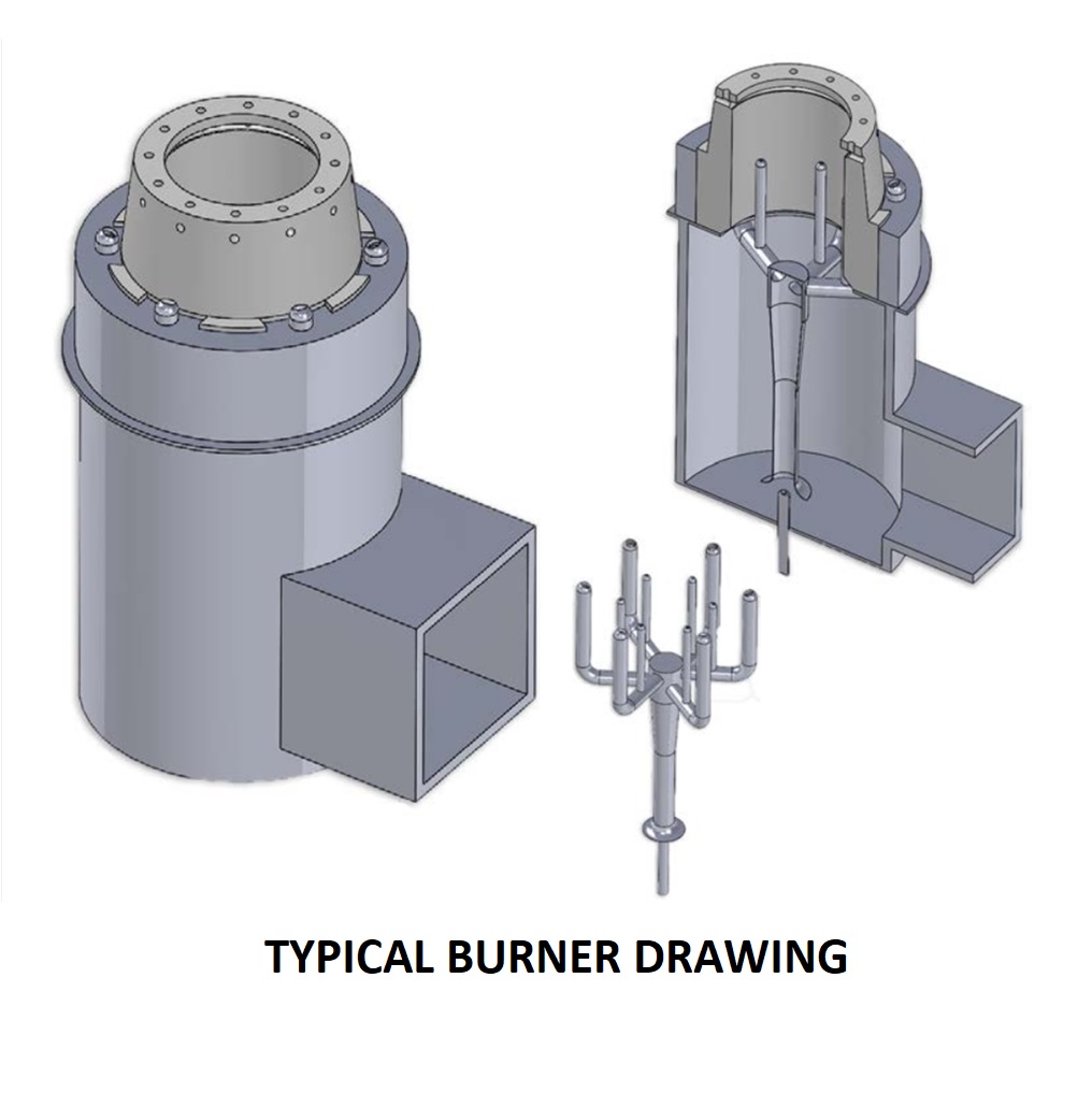
| No. of Burners | 6 | |
| Arch Pressure | mmH2O | -3.317 |
| Floor Pressure | mmH2O | -13.051 |
| ENVIRONMENTAL IMPACT | ||
| Energy Efficiency | % | 85.931 |
| Daily CO2 Emissions | kg | 66574 |
BID / PROJECT VALUE
| Total: | £ 854,035 |
SAFETY AND COMPLIANCE
| Radiant cell no. 1: The burners to tube distance seems OK (API 560) |
| Radiant cell no. 1: The burners to wall clearance seems OK (API 560) |
| Radiant cell no. 1: Burner Vertical Clearance seems OK (API 560) |
| Flame-tube impingment risk not identified |
| Radiant cell no. 1: API 560 Radiant height to width seems OK |
| Radiant cell no. 1: Single lane of burners considered |
| Stack No. 1: Auto Stack calc. has converged OK |
| Radiant section 1,Coil sect. no. 1, complies with API 530 |
| Convection section 1,Coil sect. no. 1, complies with API 530 |
| Convection section 1,Coil sect. no. 2, complies with API 530 |
| Convection section 1,Coil sect. no. 3, complies with API 530 |
| COIL ARRANGEMENT | ||||||
| Heater Section | RADIANT 1 | CONVECTION 1 | CONVECTION 1 | CONVECTION 1 | ||
| Orientation | Vertical | Horizontal | Horizontal | Horizontal | ||
| Tube OD | mm | 141.3 | 141.3 | 141.3 | 141.3 | |
| Tube Material | Carbon Steel | Carbon Steel | Carbon Steel | Carbon Steel | ||
| Tube Wall Thk | mm | Sch 40 | Sch 40 | Sch 40 | Sch 40 | |
| Max Tube Temperature | °C | 353.2 | 274.2 | 295.5 | 253.1 | |
| No. Tubes | 52 | 24 | 16 | 24 | ||
| Effective Length | m | 10.084 | 5.835 | 5.835 | 5.835 | |
| Straight Length | m | 9.685 | 6.235 | 6.235 | 6.235 |
HeaterSIM - Fired Heater Simulation Results
Online API Fired Heater Software

|
Materials & Equipment Supply
Steelwork & Fabrication |
Detail Engineering
Process & Thermal Design, Mechanical Design |
|
Shipping & Delivery
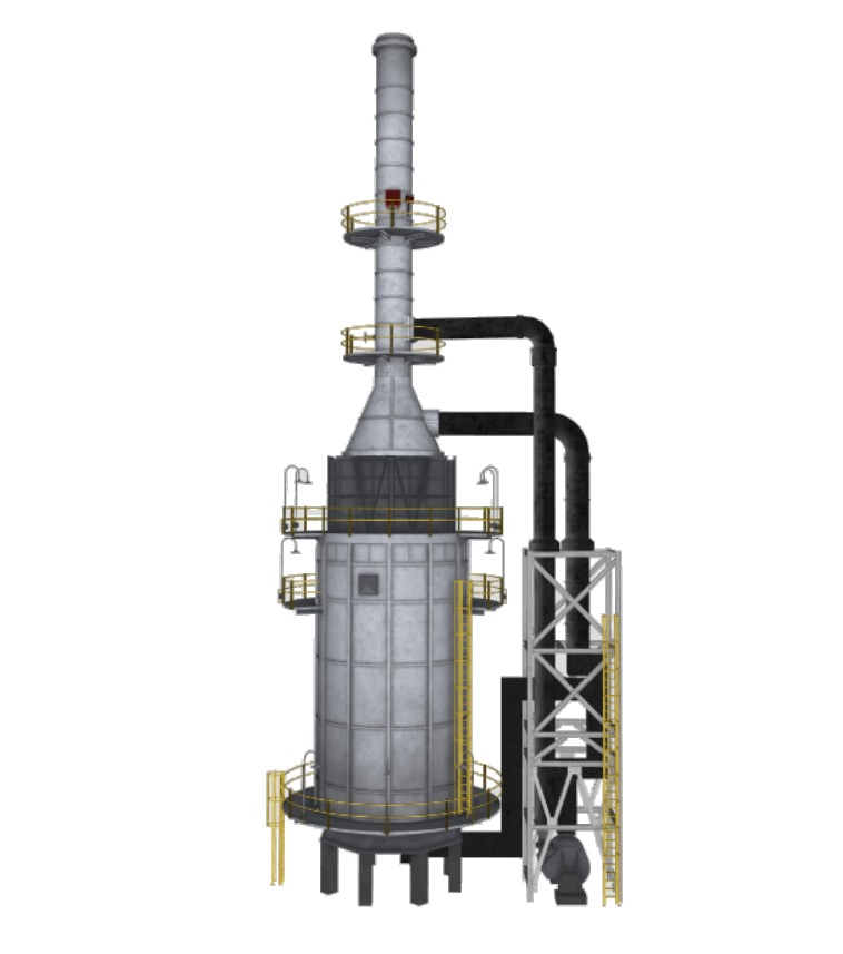
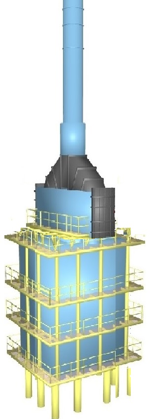
1. Radiant Section - fully modulurised |
Terms
1. Delivery: 54 weeks (28 weeks Detailed Eng. only) |
Our Partners & Vendors
Burner Vendors:
Callidus (UOP)
Greens Combustion
ICE
John Zink Hamworthy
Zeeco
Fabricators:
Vatana Phisal (VPE)
Vipco
Steelcon Malaysia
AD Demirel
Polimex
Refractory:
Morgan
Linco Baxo
Insulcon B.V.
Zibo Luzhong
| Main items | |
| Material & Equipment Supply | £ 663,074 |
| Option items | |
| Detail Engineering (by HeaterSIM) | £ 99,461 |
| Performance Guarantee | £35000 |
| Third Party Design Check | £29500 |
| Burner Performance Test | £27000 |
| Total | £854,035 |
1. Fuel Temperature as per project specifications. This value is not reported here.
2. Fuel Pressure typically ~2 barg (29 psig) at maximum burner heat release. This value is not reported here.
HeaterSIM - Fired Heater Simulation Results
Online API Fired Heater Software
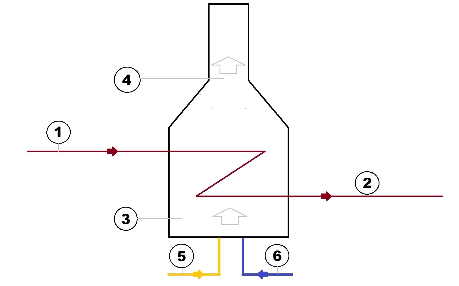
| STREAM NO. | 1 | 2 | 3 | 4 | 5 | 6 | ||
| Fluid Name | Therminol XP | Therminol XP | Radiant 1 Flue Gas | Stack 1 Flue Gas | Fuel No. 1 | Combustion Air | ||
| Flow (sec) | kg/s | 40 | 40 | 6.044 | 6.044 | 0.279 | 5.765 | |
| Flow (hr) | kg/hr | 144000 | 144000 | 21759 | 21759 | 1005 | 20754 | |
| Temperature | °C | 200 | 306.9 | 788.2 | 273.5 | Note 1 | 15.5 | |
| Pressure | kPa a | 750.1 | 410.879 | -3.317 | -1.43 | Note 2 | 101.32 |
1. Fuel Temperature as per project specifications. This value is not reported here.
2. Fuel Pressure typically ~2 barg (29 psig) at maximum burner heat release. This value is not reported here.
HeaterSIM - Fired Heater Simulation Results
Online API Fired Heater Software
Online API Fired Heater Software
| COIL ARRANGEMENT | ||||||
| Heater Section | RADIANT 1 | CONVECTION 1 | CONVECTION 1 | CONVECTION 1 | ||
| Design Code | API 530 | API 530 | API 530 | |||
| Orientation | Vertical | Horizontal | Horizontal | Horizontal | ||
| Tube OD | mm | 141.3 | 141.3 | 141.3 | 141.3 | |
| Tube Material | Carbon Steel | Carbon Steel | Carbon Steel | Carbon Steel | ||
| Tube Wall Thk | mm | Sch 40 | Sch 40 | Sch 40 | Sch 40 | |
| Tube Spacing | mm | 254 | 254 | 254 | 254 | |
| Vert. Row Spacing (Vert) | mm | N/A | 220.1 | 220.1 | 220.1 | |
| No. Tubes | 52 | 24 | 16 | 24 | ||
| Effective Length | m | 10.084 | 5.835 | 5.835 | 5.835 | |
| Straight Length | m | 9.685 | 6.235 | 6.235 | 6.235 |
| imgGAD | /Content/images/Heater560UI/NoneGAD.jpg |
| lblTopOfStackGAD | |
| lblTopStackPlatformGAD | |
| lblTopOfTransitionGAD | |
| lblTopOfConBoxGAD | |
| lblTopOfRadiantGAD | |
| lblTopOfMidRadStepOffGAD | |
| lblHearthPltfmGAD | |
| lblGradeGAD | |
| lblStackDiaGAD | |
| lblConBoxEffLengthGAD | |
| lblConBoxISwidthGAD | |
| lblRadISwidthGAD | |
| lblRadTCDGAD | |
| lblNoBurnersGAD |
| 1. DIMENSIONS TO BE CONFIRMED DURING DETAILED ENGINEERING PHASE |
| 2. LADDERS AND PLATFORMS SHALL BE IN ACCORDANCE WITH API 56O REQUIREMENTS MINIMUM AND PROJECT SPECIFICATIONS |
| 3. THIS PROPOSAL DRAWING SHOULD BE CONSIDERED AS A SKETCH AND MAY NOT BE ENTIRELY DRAWN TO SCALE |
| 4. REFRACTORY MATERIAL AND THICKNESSES SHALL BE AS PER PROJECT HEATER DATASHEET |
| 5. PLEASE REFER TO COIL CONFIGURATION AND MATERIAL WITHIN THE TABLE BELOW |
| 6. DOORS SHALL BE PROVIDED IN ACCORDANCE WITH PROJECT HEATER DATASHEET |
HeaterSIM - Fired Heater Simulation Results
Online API Fired Heater Software
| Process Name | Therminol XP | |
| Heat Duty | MW | 11.997 |
| Flow rate (sec) | kg/s | 40 |
| Pressure drop | kPa | 339.221 |
| Max. Film Temp. Calculated | °C | 344.5 |
| Max. Film Temp. Allowed | °C | 350 |
| Max Tube Average Flux Calculated (1) | W/m² | 35494 |
| Average Flux Allowed | W/m² | 22500 |
| INLET CONDITIONS | ||
| Inlet Temperature | °C | 200 |
| Inlet Pressure | kPa a | 750.1 |
| Inlet Vapour Fraction | 0 | |
| Inlet Enthalpy | kJ/kg | 584 |
| OUTLET CONDITIONS | ||
| Outlet Temperature | °C | 306.9 |
| Outlet Pressure | kPa a | 410.879 |
| Outlet Vapour Fraction | 0 | |
| Outlet Enthalpy | kJ/kg | 882 |
| If the specified or calculated fluid temperature(s) and pressure(s) are outside of the defined property grid the program will use extrapolation. Significant extrapolation may introduce inaccuracies. |
1) The max flux calculated on a individual tube basis (see tube profile results data).

HeaterSIM - Fired Heater Simulation Results
Online API Fired Heater Software

| Radiant Cell | 1 | |
| Radiant Type | ||
| Heat Duty | MW | 8.055 |
| Heat Release | MW | 13.962 |
| Arch Temp. | °C | 788.2 |
| Max Tube Temp. | °C | 353.2 |
| Tube Cirle Diameter | m | N/A |
| Average Flux | W/m² | 34605 |
| Maximum Flux | W/m² | 57481 |
| Flue Flow | kg/s | 6.044 |
| Air Flow | kg/s | 5.765 |
| Fuel Flow | kg/s | 0.279 |
| Excess Air | % | 20 |
| Air Temp. | °C | 15.5 |
| Arch Pressure | mmH2O | -3.317 |
| Floor Pressure | mmH2O | -13.051 |
| Radiant Height | m | 11.08 |
| Radiant Width | m | 4.62 |
| Radiant Length | m | 6.98 |
| No. of Burners | 6 | |
| Burner Cirle Diameter | m | N/A |
| Burner Design Firing | MW | 2.68 |
| Burner Normal Firing | MW | 2.33 |
| Burner Min Firing | MW | 0.54 |
| Burner-to-Tube Note | OK | |
| Burner-to-Wall Note | OK | |
| Burner-to-Roof Note | OK | |
| API Burner-to-Tube Dist. | m | 1.135 |
| API Burner-to-Wall Dist. | m | 1.005 |
| API Burner-to-Roof/Roof Dist | m | 7.01 |
| Floor Flux | W/m² | 432897 |
| Flame-tube impingment risk not identified |
Firing Notes
1. The Lower Heating Value (LHV) of the fuel efficiencies shall be used for efficiency calculations
2. Typical radiation heat loss value of 1.5% is used typically considered. However, in cases with a flue gas/air preheater, a value of 2.5% is normally considered.
3. Typical Excess Air values can be used as follows:
- Natural Draft - 15% excess air
- Forced Draft - 10% excess air
4. API 560 - Pressure at the Arch should be maintained at -2.5mmH2Og (-0.1inH2Og)
Tube Support Notes
1. Design temp. for tube supports should be Arch temp + 100 C (180 F)
2. No credit should be considered for shielding effect of tube supports by refractory
3. API 560 states if fuel the Vanadium + Sodium content in fuel exceeds 100ppm, supports to be either:
- 50Cr-50Ni metallurgy, without any coating
- Covered with 50 mm (2 in) of castable refractory (see API 560)
HeaterSIM - Fired Heater Simulation Results
Online API Fired Heater Software
| Radiant Type | ||
| Flue Flow | kg/s | 6.044 |
| Air Flow | kg/s | 5.765 |
| Fuel Flow | kg/s | 0.279 |
| Fuel LHV | kJ/kg | 50015 |
| Excess Air | % | 20 |
| Air Temp. | °C | 15.5 |
| CO2 | mol% | 8.06 |
| H2O | mol% | 16.06 |
| N2 | mol% | 72.67 |
| O2 | mol% | 3.21 |
| SO2 | mol% | 0 |
| Dew Point | °C | 56 |
| Fuel Mol. Wt. | 16 | |
| Flue Mol. Wt. | 27.812 | |
| Flame Temperature | °C | 1805.6 |
| Flue Gas Emissivity | 0.517 |
Notes
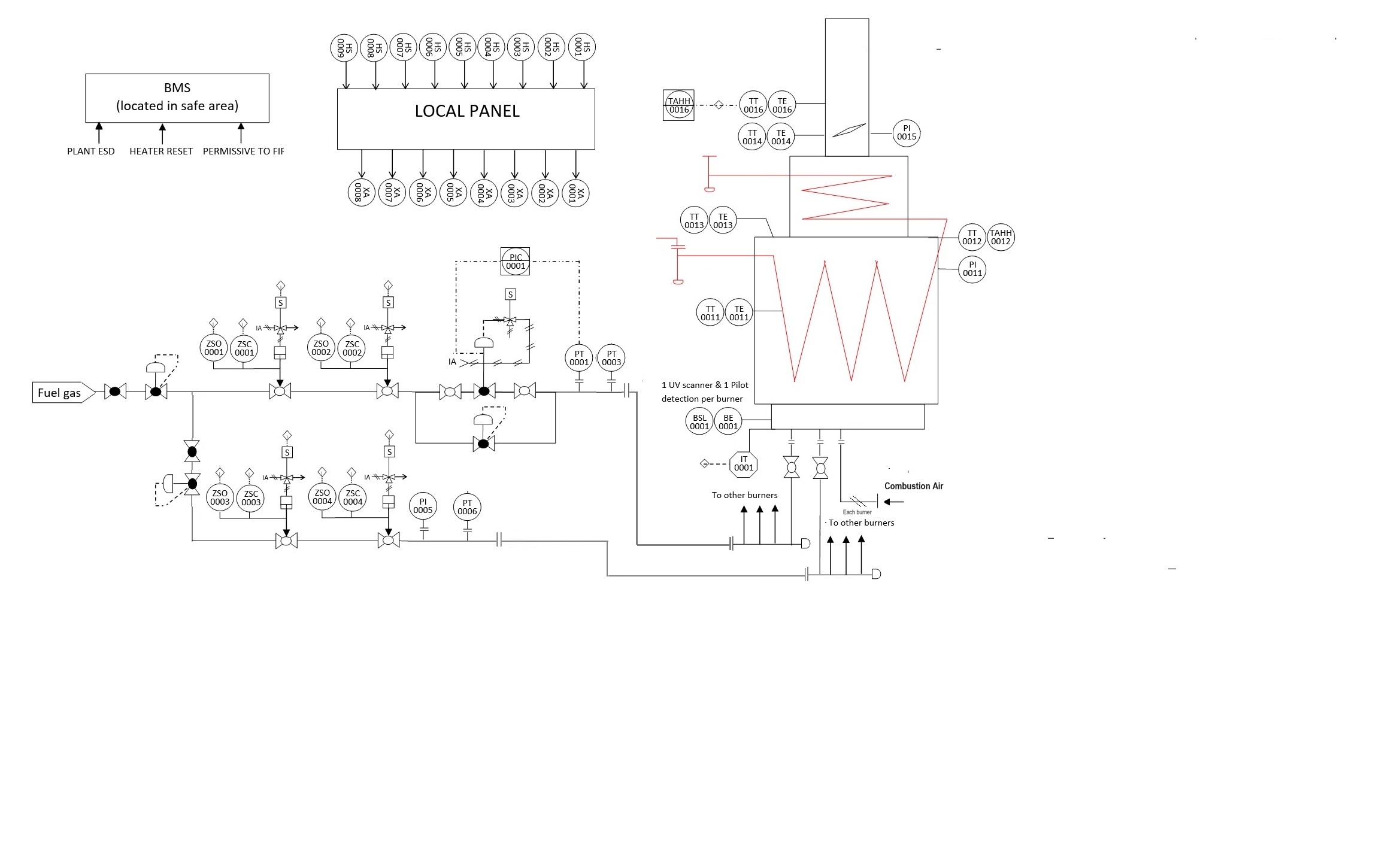
1. One UV scanner per burner is recommended (if total no. burners < 20)
2. One Pilot per burner is recommended
3. Electric spark ignition is recommended for each pilot
4. Forced draft system
Notes
1. The Lower Heating Value (LHV) of the fuel efficiencies shall be used for efficiency calculations
2. Typical radiation heat loss value of 1.5% is used typically considered. However, in cases with a flue gas/air preheater, a value of 2.5% is normally considered.
3. Typical Excess Air values can be used as follows:
- Natural Draft - 15% excess air
- Forced Draft - 10% excess air
4. API 560 - Pressure at the Arch should be maintained at -2.5mmH2Og (-0.1inH2Og)
HeaterSIM - Fired Heater Simulation Results
Online API Fired Heater Software

| Convection Sect. No. | 1 | |
| Heat Duty | MW | 3.943 |
| Max Tube Temp. | °C | 295.5 |
| Total Flue Press. Loss (ex. gain) | mmH2O | 1.22 |
| Total Press. Gain | mmH2O | 2.8 |
| Total Press. Loss (inc. gain) | mmH2O | -1.59 |
| Convection Width | m | 2.159 |
| Effective Length | m | 5.835 |
| Convection Height | m | 3.601 |
| Total No. Rows | 8 | |
| FLUE GAS DATA | ||
| Flue Gas Flow | kg/s | 6.044 |
| Flue Gas Inlet Temp. | °C | 788.2 |
| Flue Gas Outlet Temp. | °C | 273.5 |
| CO2 | mol% | 8.058337 |
| H2O | mol% | 16.05639 |
| N2 | mol% | 72.674 |
| O2 | mol% | 3.211277 |
| SO2 | mol% | 0 |
HeaterSIM - Fired Heater Simulation Results
Online API Fired Heater Software
| Conbox | Row | Duty | Temp Inlet | Temp Outlet | Enthalpy In | Enthalpy Out | Flue Density | Fin Type | Avg Flux | Max Flux | Tubes per Row | FG Mass Vel. | Flue P drop | Tube Material | Fin Material | Avg Fin Temp | Max Fin Temp |
| MW | °C | °C | kJ/kg | kJ/kg | kg/m³ | W/m² | W/m² | kg/s m² | mmH2Og | °C | °C | ||||||
| 1 | 8 | 0.25 | 309.7 | 273.5 | 331.6 | 289.5 | 0.6 | Solid | 12252 | 14814 | 8 | 1.299 | 0.175 | C.S. | C.S. | 230.7 | 240 |
| 1 | 7 | 0.38 | 362.2 | 309.7 | 394.2 | 331.6 | 0.56 | Solid | 18242 | 22010 | 8 | 1.299 | 0.188 | C.S. | C.S. | 247.6 | 261.1 |
| 1 | 6 | 0.57 | 441.2 | 362.2 | 488.9 | 394.2 | 0.5 | Solid | 27594 | 33189 | 8 | 1.299 | 0.207 | C.S. | C.S. | 273.2 | 293.3 |
| 1 | 5 | 0.65 | 529.4 | 441.2 | 597.3 | 488.9 | 0.45 | Solid | 31571 | 38896 | 8 | 1.234 | 0.164 | C.S. | C.S. | 287.2 | 313.1 |
| 1 | 4 | 0.98 | 657.3 | 529.4 | 760.3 | 597.3 | 0.39 | Solid | 47538 | 59798 | 8 | 1.234 | 0.186 | C.S. | C.S. | 328.9 | 365 |
| 1 | 3 | 0.3 | 695.3 | 657.3 | 808.6 | 760.3 | 0.36 | None | 15169 | 26497 | 8 | 1.149 | 0.095 | C.S. | None | 0 | 0 |
| 1 | 2 | 0.35 | 736.1 | 695.3 | 862.6 | 808.6 | 0.34 | None | 18517 | 32346 | 8 | 1.149 | 0.099 | C.S. | None | 0 | 0 |
| 1 | 1 | 0.44 | 788.2 | 736.1 | 923.7 | 862.6 | 0.33 | None | 25003 | 43675 | 8 | 1.149 | 0.104 | C.S. | None | 0 | 0 |
HeaterSIM - Fired Heater Simulation Results
Online API Fired Heater Software
| Conv. Box | Row | Duty | Flue Temp. IN | Flue Temp. OUT | Process | Flow | Bulk Temp. In | Bulk Temp. Out | Bulk Press. In | Bulk Press. Out | Vap. Fraction In | Vap. Fraction Out | Inlet Velocity | Inlet Crit.Vel. | Outlet Crit.Vel. | Inlet M Vel. | Outlet M Vel. | Inlet Reynolds No. | Inlet Reynolds No. |
| MW | °C | °C | °C | °C | kPa a | kPa a | m/s | m/s | m/s | kg/s m² | kg/s m² | ||||||||
| 1 | 8 | 0.25 | 309.7 | 273.5 | Therminol XP | 1 | 200 | 202.5 | 750 | 740 | 0 | 0 | 2 | 0 | 0 | 1549 | 1549 | 230808 | 236114 |
| 1 | 7 | 0.38 | 362.2 | 309.7 | Therminol XP | 2 | 202.4 | 206.1 | 740 | 730 | 0 | 0 | 2 | 0 | 0 | 1549 | 1549 | 236095 | 244332 |
| 1 | 6 | 0.57 | 441.2 | 362.2 | Therminol XP | 3 | 206.1 | 211.6 | 730 | 720 | 0 | 0 | 2 | 0 | 0 | 1549 | 1549 | 244348 | 257648 |
| 1 | 5 | 0.65 | 529.4 | 441.2 | Therminol XP | 4 | 211.6 | 217.9 | 720 | 710 | 0 | 0 | 2.1 | 0 | 0 | 1549 | 1549 | 257528 | 274124 |
| 1 | 4 | 0.98 | 657.3 | 529.4 | Therminol XP | 5 | 217.8 | 227.3 | 710 | 700 | 0 | 0 | 2.1 | 0 | 0 | 1549 | 1549 | 273847 | 301711 |
| 1 | 3 | 0.3 | 695.3 | 657.3 | Therminol XP | 6 | 227.3 | 230 | 700 | 689 | 0 | 0 | 2.1 | 0 | 0 | 1549 | 1549 | 301636 | 307864 |
| 1 | 2 | 0.35 | 736.1 | 695.3 | Therminol XP | 7 | 230 | 233.1 | 689 | 678 | 0 | 0 | 2.2 | 0 | 0 | 1549 | 1549 | 307786 | 315322 |
| 1 | 1 | 0.44 | 788.2 | 736.1 | Therminol XP | 8 | 232.9 | 236.8 | 678 | 665 | 0 | 0 | 2.4 | 0 | 0 | 1549 | 1549 | 314751 | 324521 |
| Conv. Box | Row | Coil Section | Duty | Flue Temp. IN | Vap. Fraction Out | Inlet Velocity | Outlet Velocity | Inlet Crit.Vel. | Outlet Crit.Vel. | Inlet M Vel. | Outlet M Vel. | Inlet Reynolds No. | Inlet Reynolds No. |
| MW | °C | m/s | m/s | m/s | m/s | kg/s m² | kg/s m² | ||||||
| 1 | 8 | Coil Section 3 | 0.25 | 309.7 | 0 | 2 | 2 | 0 | 0 | 1549 | 1549 | 230808 | 236114 |
| 1 | 7 | Coil Section 3 | 0.38 | 362.2 | 0 | 2 | 2 | 0 | 0 | 1549 | 1549 | 236095 | 244332 |
| 1 | 6 | Coil Section 3 | 0.57 | 441.2 | 0 | 2 | 2.1 | 0 | 0 | 1549 | 1549 | 244348 | 257648 |
| 1 | 5 | Coil Section 2 | 0.65 | 529.4 | 0 | 2.1 | 2.1 | 0 | 0 | 1549 | 1549 | 257528 | 274124 |
| 1 | 4 | Coil Section 2 | 0.98 | 657.3 | 0 | 2.1 | 2.1 | 0 | 0 | 1549 | 1549 | 273847 | 301711 |
| 1 | 3 | Coil Section 1 | 0.3 | 695.3 | 0 | 2.1 | 2.2 | 0 | 0 | 1549 | 1549 | 301636 | 307864 |
| 1 | 2 | Coil Section 1 | 0.35 | 736.1 | 0 | 2.2 | 2.4 | 0 | 0 | 1549 | 1549 | 307786 | 315322 |
| 1 | 1 | Coil Section 1 | 0.44 | 788.2 | 0 | 2.4 | 2.7 | 0 | 0 | 1549 | 1549 | 314751 | 324521 |
HeaterSIM - Fired Heater Simulation Results
Online API Fired Heater Software
| Tube No. | Loc. | Process | Bulk Temp In. | Bulk Temp Out. | Bulk Press In. | Bulk Press. Out | Enth. In | Enth. Out | Vapour Out | Tube OD | Velocity Out | Film Temp | Avg Tube Temp. | Max Tube Temp. | API Design Temp. | Avg HTC | Flow Regime | Avg Flux | Max Flux | |
| °C | °C | kPa a | kPa a | kJ/kg | kJ/kg | m/s | °C | °C | °C | °C | W/m² °C | W/m² | W/m² | |||||||
| 1 | Wall | Therminol XP | 236.8 | 239.6 | 665.3 | 716.2 | 680.9 | 688.7 | 0 | 141.3 | 2.9 | 288.3 | 291.4 | 297.3 | 312.3 | 1330.3 | Turbulent | 35494 | 58762 | |
| 2 | Wall | Therminol XP | 239.6 | 242.4 | 716.2 | 660.3 | 688.7 | 696.4 | 0 | 141.3 | 3.1 | 290.6 | 293.7 | 299.5 | 314.5 | 1341.9 | Turbulent | 35424 | 58662 | |
| 3 | Wall | Therminol XP | 242.4 | 245.1 | 660.3 | 701.8 | 696.4 | 704.1 | 0 | 141.3 | 3.4 | 292.8 | 295.9 | 301.8 | 316.8 | 1353.8 | Turbulent | 35353 | 58560 | |
| 4 | Wall | Therminol XP | 245.1 | 247.9 | 701.8 | 653.4 | 704.1 | 711.9 | 0 | 141.3 | 3.8 | 295.1 | 298.2 | 304 | 319 | 1366 | Turbulent | 35282 | 58458 | |
| 5 | Wall | Therminol XP | 247.9 | 250.7 | 653.4 | 685.3 | 711.9 | 719.6 | 0 | 141.3 | 4.2 | 297.3 | 300.4 | 306.3 | 321.3 | 1378.4 | Turbulent | 35210 | 58355 | |
| 6 | Wall | Therminol XP | 250.7 | 253.4 | 685.3 | 643.8 | 719.6 | 727.4 | 0 | 141.3 | 4.8 | 299.6 | 302.7 | 308.5 | 323.5 | 1391 | Turbulent | 35138 | 58252 | |
| 7 | Wall | Therminol XP | 253.4 | 256.2 | 643.8 | 665.8 | 727.4 | 735.1 | 0 | 141.3 | 5.4 | 301.9 | 304.9 | 310.7 | 325.7 | 1404 | Turbulent | 35066 | 58148 | |
| 8 | Wall | Therminol XP | 256.2 | 258.9 | 665.8 | 630.1 | 735.1 | 742.9 | 0 | 141.3 | 6.3 | 304.1 | 307.2 | 313 | 328 | 1417.1 | Turbulent | 34993 | 58043 | |
| 9 | Wall | Therminol XP | 258.9 | 261.7 | 630.1 | 641.1 | 742.9 | 750.6 | 0 | 141.3 | 7.6 | 306.4 | 309.4 | 315.3 | 330.3 | 1429.9 | Turbulent | 34920 | 57936 | |
| 10 | Wall | Therminol XP | 261.7 | 264.5 | 641.1 | 609.3 | 750.6 | 758.4 | 0 | 141.3 | 9.4 | 308.7 | 311.7 | 317.5 | 332.5 | 1442.9 | Turbulent | 34846 | 57828 | |
| 11 | Wall | Therminol XP | 264.5 | 267.2 | 609.3 | 606.3 | 758.4 | 766.1 | 0 | 141.3 | 12.4 | 310.9 | 314 | 319.8 | 334.8 | 1456.3 | Turbulent | 34771 | 57720 | |
| 12 | Wall | Therminol XP | 267.2 | 270 | 606.3 | 572.1 | 766.1 | 773.8 | 0 | 141.3 | 18 | 313.2 | 316.2 | 322.1 | 337.1 | 1469.9 | Turbulent | 34696 | 57611 | |
| 13 | Wall | Therminol XP | 270 | 272.7 | 572.1 | 547.9 | 773.8 | 781.6 | 0 | 141.3 | 14.8 | 315.4 | 318.5 | 324.3 | 339.3 | 1483.3 | Turbulent | 34621 | 57503 | |
| 14 | Wall | Therminol XP | 272.7 | 275.3 | 547.9 | 515.8 | 781.6 | 789.3 | 0 | 141.3 | 9.9 | 317.6 | 320.7 | 326.5 | 341.5 | 1494.7 | Turbulent | 34546 | 57395 | |
| 15 | Wall | Therminol XP | 275.3 | 277.9 | 515.8 | 520 | 789.3 | 797.1 | 0 | 141.3 | 7.5 | 319.9 | 323 | 328.7 | 343.7 | 1506.1 | Turbulent | 34471 | 57285 | |
| 16 | Wall | Therminol XP | 277.9 | 280.6 | 520 | 486.3 | 797.1 | 804.8 | 0 | 141.3 | 6 | 322.1 | 325.2 | 330.9 | 345.9 | 1517.8 | Turbulent | 34396 | 57175 | |
| 17 | Wall | Therminol XP | 280.6 | 283.2 | 486.3 | 505.3 | 804.8 | 812.6 | 0 | 141.3 | 5 | 324.3 | 327.4 | 333.1 | 348.1 | 1529.6 | Turbulent | 34321 | 57064 | |
| 18 | Wall | Therminol XP | 283.2 | 285.8 | 505.3 | 464.9 | 812.6 | 820.3 | 0 | 141.3 | 4.3 | 326.6 | 329.6 | 335.4 | 350.4 | 1541.7 | Turbulent | 34245 | 56952 | |
| 19 | Wall | Therminol XP | 285.8 | 288.5 | 464.9 | 496.1 | 820.3 | 828.1 | 0 | 141.3 | 3.8 | 328.8 | 331.9 | 337.6 | 352.6 | 1553.9 | Turbulent | 34168 | 56840 | |
| 20 | Wall | Therminol XP | 288.5 | 291.1 | 496.1 | 447.7 | 828.1 | 835.8 | 0 | 141.3 | 3.4 | 331 | 334.1 | 339.8 | 354.8 | 1566.4 | Turbulent | 34091 | 56726 | |
| 21 | Wall | Therminol XP | 291.1 | 293.7 | 447.7 | 489.8 | 835.8 | 843.6 | 0 | 141.3 | 3.1 | 333.2 | 336.3 | 342 | 357 | 1579.2 | Turbulent | 34014 | 56612 | |
| 22 | Wall | Therminol XP | 293.7 | 296.4 | 489.8 | 433 | 843.6 | 851.3 | 0 | 141.3 | 2.8 | 335.5 | 338.5 | 344.2 | 359.2 | 1592.1 | Turbulent | 33936 | 56497 | |
| 23 | Wall | Therminol XP | 296.4 | 299 | 433 | 485.4 | 851.3 | 859 | 0 | 141.3 | 2.6 | 337.7 | 340.8 | 346.5 | 361.5 | 1605.4 | Turbulent | 33858 | 56381 | |
| 24 | Wall | Therminol XP | 299 | 301.6 | 485.4 | 420 | 859 | 866.8 | 0 | 141.3 | 2.4 | 339.9 | 343 | 348.7 | 363.7 | 1618.9 | Turbulent | 33779 | 56264 | |
| 25 | Wall | Therminol XP | 301.6 | 304.3 | 420 | 482.3 | 866.8 | 874.5 | 0 | 141.3 | 2.3 | 342.2 | 345.2 | 350.9 | 365.9 | 1632.6 | Turbulent | 33700 | 56147 | |
| 26 | Wall | Therminol XP | 304.3 | 306.9 | 482.3 | 410.9 | 874.5 | 882.3 | 0 | 141.3 | 2.3 | 344.5 | 347.5 | 353.2 | 368.2 | 1645.4 | Turbulent | 33619 | 56025 |
| Flame-tube impingment risk not identified |
HeaterSIM - Fired Heater Simulation Results
Online API Fired Heater Software
| Conv. Box | Tube No. | Coil Sect. | Row | Process | Bulk Temp. In | Bulk Temp. Out | Press. In | Press. Out | Enth. In | Enth. Out | Vapour Fraction | Tube OD | Velocity | Film | Avg Tube Temp. | Max Tube Temp. | API Design Temp. | Avg HTC | Fin Type | Flow Regime | Tube Mat. | Avg Flux | Max Flux |
| °C | °C | kPa a | kPa a | kJ/kg | kJ/kg | m/s | °C | °C | °C | °C | W/m² °C | W/m² | W/m² | ||||||||||
| 1 | 1 | 3 | 8 | Therminol XP | 200 | 200.6 | 750.1 | 747.6 | 583.6 | 585.2 | 0 | 141.3 | 2 | 218 | 219 | 220.6 | 235.6 | 1095.7 | Solid | Turbulent | C.S. | 12352 | 17335 |
| 1 | 2 | 3 | 8 | Therminol XP | 200.6 | 201.2 | 747.6 | 745.1 | 585.2 | 586.8 | 0 | 141.3 | 2 | 218.5 | 219.5 | 221 | 236 | 1098.5 | Solid | Turbulent | C.S. | 12267 | 17215 |
| 1 | 3 | 3 | 8 | Therminol XP | 201.2 | 201.8 | 745.1 | 742.6 | 586.8 | 588.3 | 0 | 141.3 | 2 | 218.9 | 219.9 | 221.5 | 236.5 | 1101.3 | Solid | Turbulent | C.S. | 12181 | 17095 |
| 1 | 4 | 3 | 8 | Therminol XP | 201.8 | 202.5 | 742.6 | 740.1 | 588.3 | 589.9 | 0 | 141.3 | 2 | 219.4 | 220.3 | 221.9 | 236.9 | 1104.1 | Solid | Turbulent | C.S. | 12096 | 16975 |
| 1 | 5 | 3 | 7 | Therminol XP | 202.4 | 203.4 | 740.1 | 737.5 | 589.9 | 592.3 | 0 | 141.3 | 2 | 228.7 | 230.2 | 232.5 | 247.5 | 1121 | Solid | Turbulent | C.S. | 18395 | 25780 |
| 1 | 6 | 3 | 7 | Therminol XP | 203.4 | 204.3 | 737.5 | 735 | 592.3 | 594.6 | 0 | 141.3 | 2 | 229.4 | 230.8 | 233.2 | 248.2 | 1125 | Solid | Turbulent | C.S. | 18265 | 25598 |
| 1 | 7 | 3 | 7 | Therminol XP | 204.3 | 205.2 | 735 | 732.5 | 594.6 | 597 | 0 | 141.3 | 2 | 230 | 231.4 | 233.8 | 248.8 | 1129 | Solid | Turbulent | C.S. | 18135 | 25415 |
| 1 | 8 | 3 | 7 | Therminol XP | 205.2 | 206.1 | 732.5 | 730 | 597 | 599.3 | 0 | 141.3 | 2 | 230.7 | 232.1 | 234.4 | 249.4 | 1133 | Solid | Turbulent | C.S. | 18005 | 25233 |
| 1 | 9 | 3 | 6 | Therminol XP | 206.1 | 207.5 | 730 | 727.5 | 599.4 | 602.9 | 0 | 141.3 | 2.1 | 244.7 | 246.9 | 250.5 | 265.5 | 1154.8 | Solid | Turbulent | C.S. | 27831 | 38924 |
| 1 | 10 | 3 | 6 | Therminol XP | 207.5 | 208.9 | 727.5 | 725 | 602.9 | 606.5 | 0 | 141.3 | 2.1 | 245.6 | 247.8 | 251.3 | 266.3 | 1161.1 | Solid | Turbulent | C.S. | 27628 | 38640 |
| 1 | 11 | 3 | 6 | Therminol XP | 208.9 | 210.3 | 725 | 722.4 | 606.5 | 610.1 | 0 | 141.3 | 2.1 | 246.5 | 248.7 | 252.2 | 267.2 | 1167.4 | Solid | Turbulent | C.S. | 27425 | 38355 |
| 1 | 12 | 3 | 6 | Therminol XP | 210.3 | 211.6 | 722.4 | 719.9 | 610.1 | 613.7 | 0 | 141.3 | 2.1 | 247.4 | 249.6 | 253.1 | 268.1 | 1173.9 | Solid | Turbulent | C.S. | 27221 | 38071 |
| 1 | 13 | 2 | 5 | Therminol XP | 211.6 | 213.2 | 719.9 | 717.4 | 613.5 | 617.6 | 0 | 141.3 | 2.1 | 255 | 257.6 | 261.8 | 276.8 | 1189.8 | Solid | Turbulent | C.S. | 31803 | 45155 |
| 1 | 14 | 2 | 5 | Therminol XP | 213.2 | 214.8 | 717.4 | 714.8 | 617.6 | 621.7 | 0 | 141.3 | 2.1 | 256.1 | 258.7 | 262.8 | 277.8 | 1197.5 | Solid | Turbulent | C.S. | 31615 | 44888 |
| 1 | 15 | 2 | 5 | Therminol XP | 214.8 | 216.3 | 714.8 | 712.3 | 621.7 | 625.8 | 0 | 141.3 | 2.1 | 257.2 | 259.7 | 263.9 | 278.9 | 1205.2 | Solid | Turbulent | C.S. | 31427 | 44622 |
| 1 | 16 | 2 | 5 | Therminol XP | 216.3 | 217.9 | 712.3 | 709.8 | 625.8 | 629.9 | 0 | 141.3 | 2.1 | 258.2 | 260.8 | 264.9 | 279.9 | 1213.1 | Solid | Turbulent | C.S. | 31240 | 44355 |
| 1 | 17 | 2 | 4 | Therminol XP | 217.8 | 220.2 | 709.8 | 707.2 | 629.6 | 635.8 | 0 | 141.3 | 2.1 | 280.9 | 285 | 291.4 | 306.4 | 1252.4 | Solid | Turbulent | C.S. | 47917 | 68970 |
| 1 | 18 | 2 | 4 | Therminol XP | 220.2 | 222.6 | 707.2 | 704.7 | 635.8 | 641.9 | 0 | 141.3 | 2.1 | 282.3 | 286.3 | 292.7 | 307.7 | 1264.3 | Solid | Turbulent | C.S. | 47606 | 68523 |
| 1 | 19 | 2 | 4 | Therminol XP | 222.6 | 225 | 704.7 | 702.1 | 641.9 | 648.1 | 0 | 141.3 | 2.1 | 283.8 | 287.7 | 294.1 | 309.1 | 1276.5 | Solid | Turbulent | C.S. | 47296 | 68076 |
| 1 | 20 | 2 | 4 | Therminol XP | 225 | 227.3 | 702.1 | 699.6 | 648.1 | 654.2 | 0 | 141.3 | 2.1 | 285.2 | 289.1 | 295.5 | 310.5 | 1289 | Solid | Turbulent | C.S. | 46985 | 67629 |
| 1 | 21 | 1 | 3 | Therminol XP | 227.3 | 228 | 699.6 | 697 | 654.1 | 656 | 0 | 141.3 | 2.1 | 250.6 | 252.2 | 254.4 | 269.4 | 1245.4 | None | Turbulent | C.S. | 14647 | 25584 |
| 1 | 22 | 1 | 3 | Therminol XP | 228 | 228.6 | 697 | 694.3 | 656 | 657.9 | 0 | 141.3 | 2.2 | 251.2 | 252.8 | 255 | 270 | 1248.1 | None | Turbulent | C.S. | 14625 | 25547 |
| 1 | 23 | 1 | 3 | Therminol XP | 228.6 | 229.3 | 694.3 | 691.7 | 657.9 | 659.8 | 0 | 141.3 | 2.2 | 251.8 | 253.4 | 255.6 | 270.6 | 1250.8 | None | Turbulent | C.S. | 14604 | 25510 |
| 1 | 24 | 1 | 3 | Therminol XP | 229.3 | 230 | 691.7 | 689 | 659.8 | 661.7 | 0 | 141.3 | 2.2 | 252.4 | 254 | 256.2 | 271.2 | 1253.6 | None | Turbulent | C.S. | 14583 | 25473 |
| 1 | 25 | 1 | 2 | Therminol XP | 230 | 230.8 | 689 | 686.2 | 661.6 | 663.8 | 0 | 141.3 | 2.3 | 256.9 | 258.8 | 261.5 | 276.5 | 1262.3 | None | Turbulent | C.S. | 17173 | 29997 |
| 1 | 26 | 1 | 2 | Therminol XP | 230.8 | 231.5 | 686.2 | 683.4 | 663.8 | 666 | 0 | 141.3 | 2.3 | 257.6 | 259.5 | 262.1 | 277.1 | 1265.5 | None | Turbulent | C.S. | 17147 | 29952 |
| 1 | 27 | 1 | 2 | Therminol XP | 231.5 | 232.3 | 683.4 | 680.5 | 666 | 668.3 | 0 | 141.3 | 2.4 | 258.3 | 260.2 | 262.8 | 277.8 | 1268.8 | None | Turbulent | C.S. | 17121 | 29907 |
| 1 | 28 | 1 | 2 | Therminol XP | 232.3 | 233.1 | 680.5 | 677.6 | 668.3 | 670.5 | 0 | 141.3 | 2.4 | 259 | 260.8 | 263.5 | 278.5 | 1272.1 | None | Turbulent | C.S. | 17095 | 29862 |
| 1 | 29 | 1 | 1 | Therminol XP | 232.9 | 233.9 | 677.7 | 674.7 | 669.8 | 672.6 | 0 | 141.3 | 2.5 | 266 | 268.4 | 271.7 | 286.7 | 1284.9 | None | Turbulent | C.S. | 21458 | 37483 |
| 1 | 30 | 1 | 1 | Therminol XP | 233.9 | 234.9 | 674.7 | 671.7 | 672.6 | 675.4 | 0 | 141.3 | 2.5 | 266.9 | 269.2 | 272.5 | 287.5 | 1289.1 | None | Turbulent | C.S. | 21425 | 37424 |
| 1 | 31 | 1 | 1 | Therminol XP | 234.9 | 235.9 | 671.7 | 668.5 | 675.4 | 678.1 | 0 | 141.3 | 2.6 | 267.7 | 270 | 273.3 | 288.3 | 1293.3 | None | Turbulent | C.S. | 21391 | 37366 |
| 1 | 32 | 1 | 1 | Therminol XP | 235.9 | 236.8 | 668.5 | 665.3 | 678.1 | 680.9 | 0 | 141.3 | 2.7 | 268.5 | 270.9 | 274.2 | 289.2 | 1297.6 | None | Turbulent | C.S. | 21358 | 37308 |
HeaterSIM - Fired Heater Simulation Results
Online API Fired Heater Software
| Heater Section | RADIANT 1 | CONVECTION 1 | CONVECTION 1 | CONVECTION 1 | ||
| Coil Section | Coil Section 1 | Coil Section 1 | Coil Section 2 | Coil Section 3 | ||
| Process Name | Process 1: Therminol XP | Process 1: Therminol XP | Process 1: Therminol XP | Process 1: Therminol XP | ||
| Tube OD | mm | 141.3 | 141.3 | 141.3 | 141.3 | |
| Tube Material | Carbon Steel | Carbon Steel | Carbon Steel | Carbon Steel | ||
| Tube Wall Thk | mm | Sch 40 | Sch 40 | Sch 40 | Sch 40 | |
| Max Tube Temperature | °C | 353.2 | 274.2 | 295.5 | 253.1 | |
| Tube Temperature Margin | °C | 15 | 15 | 15 | 15 | |
| Design Tube Temperature | °C | 368.2 | 289.2 | 310.5 | 268.1 | |
| Design Tube Pressure | kPa | 2000.2 | 2000.2 | 2000.2 | ||
| Design Code | API 530 | API 530 | API 530 | |||
| Tube Thk. Comment | Tube Thk. OK (API 530) | Tube Thk. OK (API 530) | Tube Thk. OK (API 530) | Tube Thk. OK (API 530) | ||
| No. Tubes | 52 | 24 | 16 | 24 | ||
| No. Tubes Per Row | 8 | 8 | 8 | |||
| No. Passes | 2 | 2 | 2 | 2 | ||
| Effective Length | m | 10.084 | 5.835 | 5.835 | 5.835 | |
| Straight Length | m | 9.685 | 6.235 | 6.235 | 6.235 | |
| No. Rows | 3 | 2 | 3 | |||
| Tube Spacing | mm | 254 | 254 | 254 | 254 | |
| Vert. Row Spacing (Vert) | mm | N/A | 220.1 | 220.1 | 220.1 | |
| Coil Alignment | Staggered | Staggered | Staggered | |||
| Orientation | Vertical | Horizontal | Horizontal | Horizontal | ||
| Tube Area | m² | 232.77 | 62.13 | 325.88 | 801.84 | |
| Intermediate Supports | 0 / 0 | 1 / 1 | 1 / 1 | 1 / 1 | ||
| Corbel Width | m | 1/2 Tube Space | 1/2 Tube Space | 1/2 Tube Space | ||
| Fin Type | None | Solid | Solid | |||
| Fin Material | None | Carbon Steel | Carbon Steel | |||
| Fin Height | mm | 19.1 | 25.4 | |||
| Fin Thickness | mm | 1.3 | 1.3 | |||
| Serrated Fin Wn | ||||||
| Fin Density | fins/m | 157 | 197 |
| Radiant section 1,Coil sect. no. 1, complies with API 530 |
| Convection section 1,Coil sect. no. 1, complies with API 530 |
| Convection section 1,Coil sect. no. 2, complies with API 530 |
| Convection section 1,Coil sect. no. 3, complies with API 530 |
Notes
1. For vertical-tube, vertical-fired heaters, the maximum radiant straight tube length shall be 18,3 m (60 ft)
2. For horizontal heaters fired from both ends, the maximum radiant straight tube length shall be 12,2 m (40 ft)
3. API 560 - The tube-wall thickness should be in accordance with ISO 13704 (unless otherwise mutually agreed)
4. API 560 - Tube-wall thicknesses should include the minimum allowances for corrosion and/or erosion as follows:
- Carbon Steel Tubes - 3mm (0.125in)
- P Grade Tubes Tubes - 2mm (0.08in)
- Stainless Steel Tubes - 1mm (0.04in)
5. The unsupported length of horizontal tubes shall not exceed 35 times the outside diameter or 6 m (20 ft), whichever is less.
Calculation of Heater-tube Thickness in Petroleum Refineries
HeaterSIM - Fired Heater Simulation Results
Online API Fired Heater Software
| Location | RADIANT | CONVECTION | CONVECTION | CONVECTION | |
| Coil/Piping Section | Coil Section 1 | Coil Section 1 | Coil Section 2 | Coil Section 3 | |
| Design Pressure | kPa g | 2000.2 | 2000.2 | 2000.2 | 2000.2 |
| Max Operating Pressure | kPa g | 750.1 | 750.1 | 750.1 | 750.1 |
| Design Temperature | °C | 368.1863 | 289.1645 | 310.4541 | 268.0912 |
| Tube Material | Carbon Steel | Carbon Steel | Carbon Steel | Carbon Steel | |
| Tube Outside Diameter | 141.3 | 141.3 | 141.3 | 141.3 | |
| Tube Thickness | mm | 6.55 | 6.55 | 6.55 | 6.55 |
| Corrosion Allowance | mm | 3 | 3 | 3 | 3 |
| Design Life | hours | 100000 | 100000 | 100000 | 100000 |
TUBE DESIGN RESULTS | |||||
| Specified Tube Thickness | mm | 6.55 | 6.55 | 6.55 | 6.55 |
| ELASTIC DESIGN | |||||
| Elastic Allowable Stress | kPa | 109341.3 | 121921.6 | 118864.9 | 124579.5 |
| Elastic Stress Thickness | mm | 1.2807 | 1.1496 | 1.1789 | 1.1253 |
| Elastic Min. Tube Thickness | mm | 4.28 | 4.15 | 4.18 | 4.13 |
| Elastic Average Tube Thickness | mm | 4.89 | 4.74 | 4.78 | 4.71 |
| Elastic Design Comment | Thickness is OK | Thickness is OK | Thickness is OK | Thickness is OK | |
| RUPTURE DESIGN | |||||
| Rupture Allowable Stress | 0 | 0 | 0 | 0 | |
| Rupture n factor | 0 | 0 | 0 | 0 | |
| Rupture Stress Thickness | mm | 0 | 0 | 0 | 0 |
| Rupture Min. Tube Thickness | mm | 0 | 0 | 0 | 0 |
| Rupture Avg. Tube Thickness | mm | 0 | 0 | 0 | 0 |
| B factor | 0 | 0 | 0 | 0 | |
| Corrosion Factor Fcorr | 0 | 0 | 0 | 0 | |
| Rupture Design Comment | Not applicable | Not applicable | Not applicable | Not applicable | |
HeaterSIM - Fired Heater Simulation Results
Online API Fired Heater Software
| Stack Height | m | 15 |
| Stack Diameter | m | 1.48 |
| Cone Diameter | m | 1.484 |
| Cone Height | m | 0.5 |
| Actual Exit Velocity | m/s | 6.5 |
| Design Exit Velocity | m/s | 7.8 |
| Flue Gas Temp. | °C | 273.5 |
| Flue Gas Flow | kg/s | 6.044 |
| Steel Area | m² | 69.925 |
| Stack Entry Pressure | mmH2O | -1.43 |
| CO2 | mol% | 8.06 |
| H2O | mol% | 16.06 |
| N2 | mol% | 72.67 |
| O2 | mol% | 3.21 |
| SO2 | mol% | 0 |
| Draft at Stack Base | mmH2Og | -2.5 |
| Draft at Arch | mmH2Og | -2.5 |
| Draft at Floor | mmH2Og | 0 |

| Stack No. 1: Auto Stack calc. has converged OK |
HeaterSIM - Fired Heater Simulation Results
Online API Fired Heater Software
| Hot-Face | Hot-Face | Hot-Face | Back-Up | Back-Up | Back-Up | Material | ||||||||
| Flue Temp. | Material | Thickness | Conductivity | Material | Thickness | Conductivity | Allowable Flux | Actual Flux | Design Temp. | Anchor Type | Casing Temp. | Comment | ||
| °C | mm | W/mK | mm | W/mK | W/m² | W/m² | °C | |||||||
| RADIANT FLOOR 1 | 738.2 | MW Castable | 75 | 0.4 | ULW Castable | 150 | 0.14 | 732.5 | 506.9 | 1400 | V Y Anchors | 73.3 | Refrac. thickness OK | |
| RADIANT WALL 1 | 570.7 | Fibre (High Density) | 75 | 0.1 | None | 0 | 0 | 732.8 | 487.8 | 1260 | Twistlock Pins | 66 | Refrac. thickness OK | |
| RADIANT ARCH 1 | 788.2 | Fibre (High Density) | 87.7 | 0.1 | None | 0 | 0 | 824 | 807.2 | 1260 | Twistlock Pins | 80.6 | Refrac. thickness OK | |
| CONVECTION SIDEWALL 1 | 530.8 | LW Castable | 75 | 0.3 | ULW Castable | 75 | 0.13 | 732.8 | 541.5 | 1100 | V Y Anchors | 69.5 | Refrac. thickness OK | |
| STACK 1 | 273.5 | LW Castable | 75.4 | 0.3 | None | 0 | 0 | 732.8 | 656.1 | 1100 | V Y Anchors | 76.4 | Refrac. thickness OK | |
| No thermal calc. carried out for Convection End Wall (Tubesheets) or Headerbox sections |
Notes
1. Environmentally friendly body-soluble fibre is the recommended choice for fire insulation
2. HW and MW Castable is strong enough to be used on floor without a top brick layer
3. Ceramic fibre insulation are typically used in all areas except stack and ducting.
4. Ceramic fibre not suitable for convection sections with sootblowers or steam lances are used for cleaning.
5. Vapour barrier protective coating is required behind all areas lined with ceramic fibre
6. SS foil barrier is required for ceramic fibre lined areas if the sulphur content exceeds 500ppm by mass.